Proton exchange membrane (PEM) water electrolysis technology (PEMEL) is one of the more mature water electrolysis hydrogen production solutions in the current industrial and research fields.
1. Working principle of PEM electrolyzer
The PEM electrolyzer uses electricity to decompose water into hydrogen and oxygen. The core process is as follows:
1. Water enters the anode side through the flow channels of the bipolar half plate (BPHP).
2. Water diffuses through the porous transport layer (PTL) to the anode surface of the catalyst coated membrane (CCM).
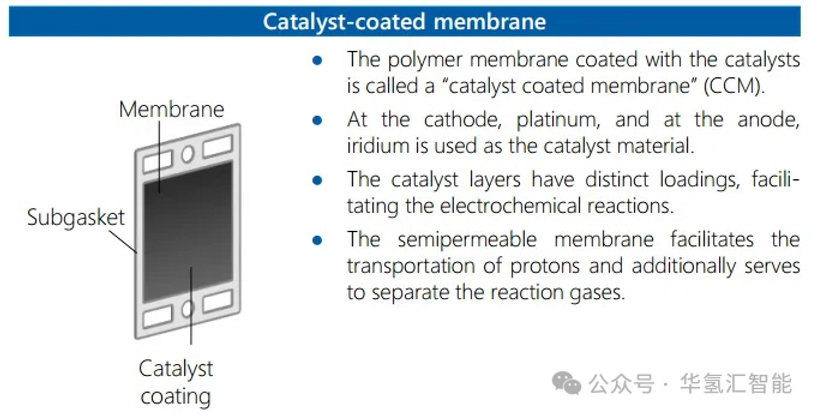
3. Under the action of the anode catalyst, water molecules are oxidized to produce protons (H⁺) and oxygen. The protons are conducted through the proton exchange membrane to the cathode side.
4. The electrons are conducted to the cathode side through the external circuit, combined with the arriving protons (H⁺), and reduced to generate hydrogen on the cathode catalyst.
5. Finally, the hydrogen and oxygen produced by the reaction are purified and stored separately for subsequent use.

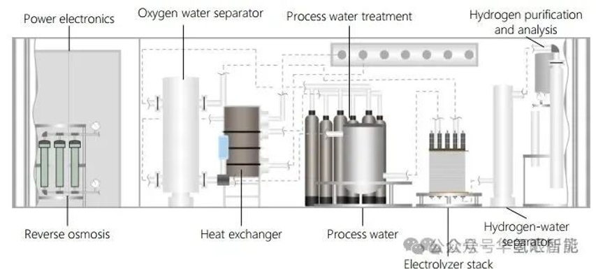
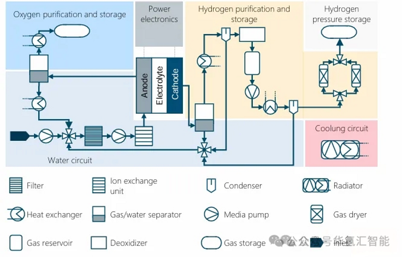
2. PEM electrolysis system structure
A complete PEM electrolysis system typically contains six key functional areas (the specific configuration may vary depending on the system):
Water circulation: Deionized water is provided to the electrolyzer. Tap water is treated (filtration, ion exchange) to achieve the required quality. Incomplete reactions can cause water to be carried over into the oxygen and hydrogen products. This water is recovered through a separator and condenser and returned to the electrolyzer.
Hydrogen Purification and Storage: The cathode product contains hydrogen, water, and trace amounts of oxygen. It is purified through a gas/water separator, condenser, deoxygenator, and pressure swing adsorption (PSA). The purified hydrogen is pressurized by a compressor, cooled by a heat exchanger, and then stored.
Oxygen purification and storage: High-purity oxygen produced at the anode is separated from the water cycle by a gas/water separator. After removing process heat, the oxygen can be stored or sold as an industrial feedstock.
Cooling circuit: Heat exchangers are used to remove process heat generated by the electrolyser stack, compressor pumps, etc. Cooling water is circulated through a pump, releasing the heat to an external cooling system.
Power electronics: These devices provide the DC power required by the electrolytic stack. They typically convert AC power from the grid into DC power after passing it through a transformer to adjust the voltage.
3. PEM electrolyzer system production process
1. Comparison of PEMEL and PEMFC processes
There are significant differences and similarities between the production processes of PEM electrolyzers (PEMEL) and proton exchange membrane fuel cells (PEMFC):
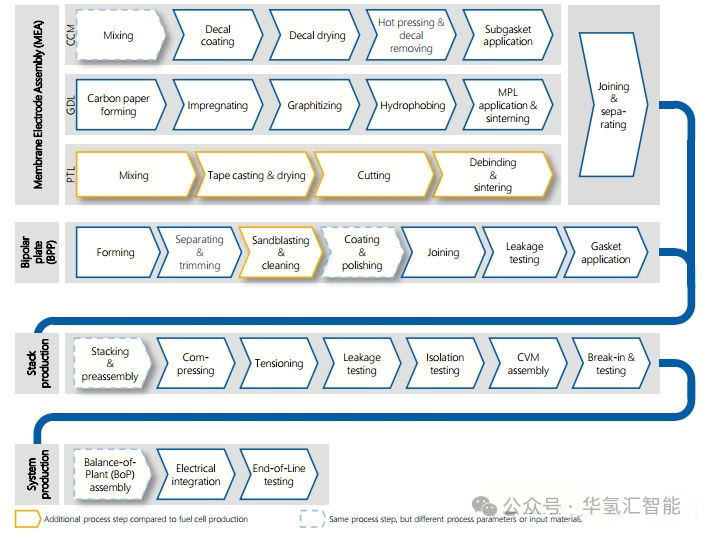
2. Key differences in the process chain
Component level:
Anode catalyst: PEMEL anode requires an iridium (Ir)-based catalyst (high potential requirement), while PEMFC typically uses platinum (Pt).
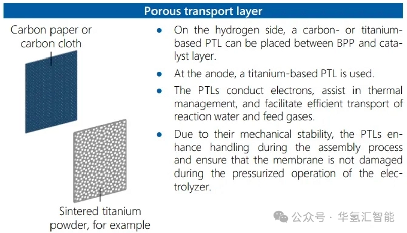
Anode diffusion layer: The PEMEL anode requires a titanium-based porous transport layer (PTL), and the cathode can use a carbon-based gas diffusion layer (GDL) similar to that of PEMFC.
Battery stacking level: PEMEL single cell area is usually larger, which places higher requirements on component processing and stacking process.
System assembly level:
PEMFC system assembly often adopts the continuous workstation assembly line model of the automotive industry.
The assembly of large-scale PEMEL systems is closer to the integration of large-scale engineering equipment, and containerized solutions (such as separation and drying units) are often used.
4. Overview of PEM electrolyzer core components
1. Catalyst Coated Membrane (CCM) Manufacturing
CCM is the core where the electrolysis reaction occurs.
2. Porous Tra
nsport Layer (PTL)
The PTL (especially the titanium-based anodic PTL) ensures reactant transport, product removal, and current conduction.
3. Bipolar Plate (BP)
The bipolar plates form the flow field, separate the gas chambers, and conduct current and heat.

5. CCM Component Production
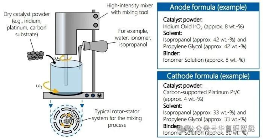
1. Slurry mixing
· Cathode catalyst ink: mainly composed of carbon support (such as carbon black) and platinum (Pt) catalyst.
· Anode catalyst ink: uses iridium oxide (IrO₂) as a catalyst.
· Ink preparation: The catalyst powder is mixed with solvents, binders (such as Nafion, to promote proton conduction) and other additives to form a uniform dispersion.
· Process: The cathode website and anode inks are stirred and mixed separately until the desired uniform viscosity is achieved.
ree
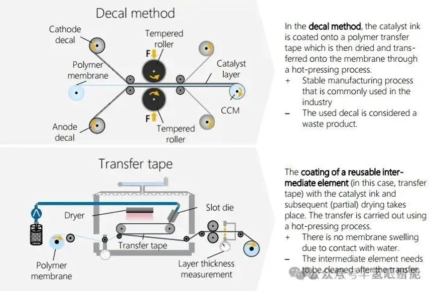
2. CCM Manufacturing: Coating Methods and Research
CCM coating methods are mainly divided into indirect method and direct method:
· Indirect method (such as transfer printing): The catalyst slurry is first coated on the release substrate and then transferred to the membrane after drying.
· Direct method (mainstream): The catalyst slurry is directly coated on the functional layer (mainly the membrane).
6. PTL component production
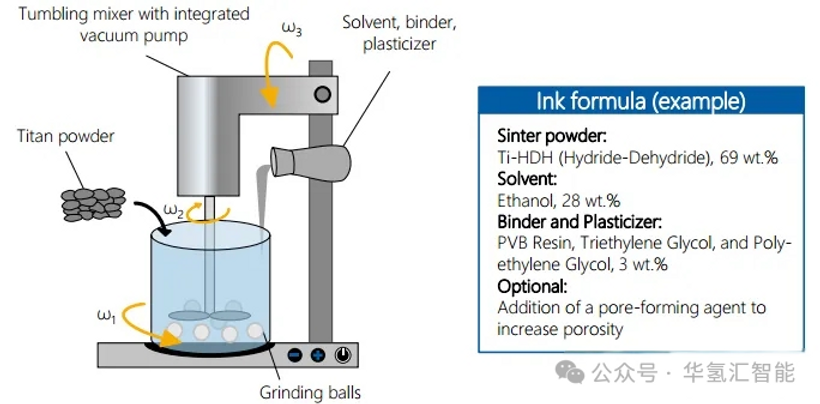
1. Mixing
Titanium-based PTL slurry preparation:
· The binder, plasticizer and solvent are uniformly dispersed in a tumble mixer.
· Titanium metal powder is added and grinding balls can be used to assist dispersion.
· A vacuum pump assists in removing air bubbles generated during the mixing process.

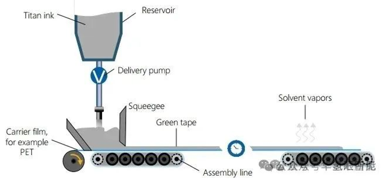
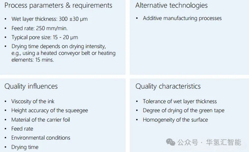
2. Casting and drying
· Purpose: To evenly coat the titanium slurry on a flat copyright film.
· Process: The slurry is pumped under the doctor blade. The gap between the doctor blade and the copyright film controls the wet film thickness. A thin layer is formed as the conveyor moves.
· Drying: The wet film is dried on a conveyor belt under exposure to the environment or specific conditions to evaporate most of the solvent.

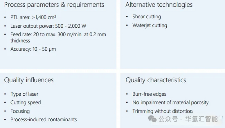
3. Cutting
· Use a laser cutter.
· The laser beam is focused onto the drying tape through a lens.
· The XY gantry precisely controls the movement of the cutting head.
· A high-energy laser cuts the separated material along the predetermined PTL geometry.

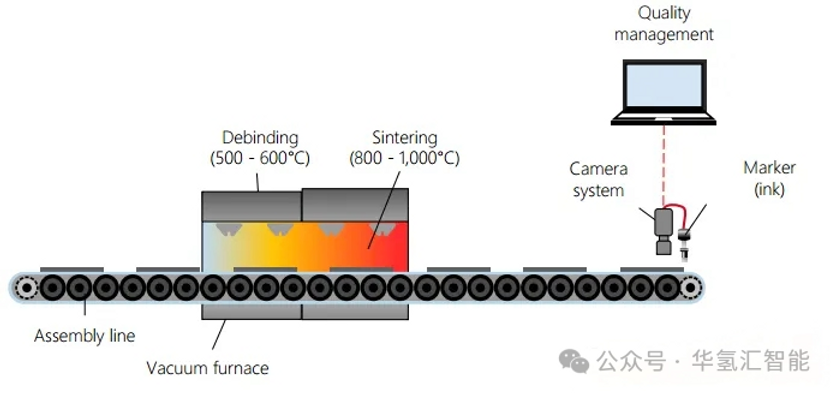
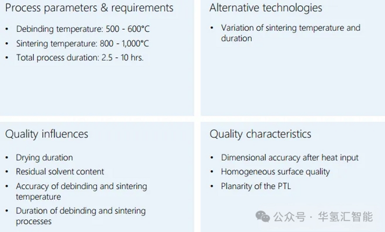
4. Debinding and sintering
· Degreasing: Gradually increase the temperature to remove organic additives (binders, plasticizers, etc.) in the slurry.
· Sintering: This process is carried out at a higher temperature to fuse the titanium particles and form the final porous structure. This process may cause the PTL to shrink, and subsequent laser cutting is often required to ensure dimensional accuracy.
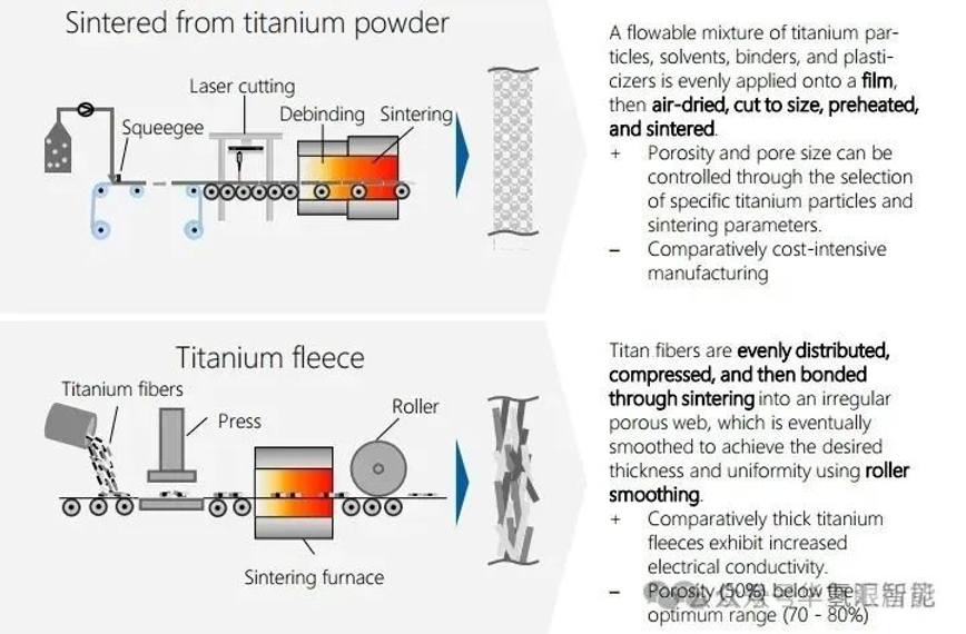
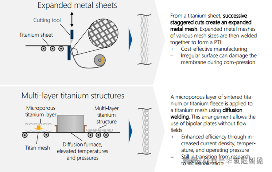
5. Summary of PTL main production methods
The industrial manufacturing methods of titanium-based PTL (primarily for anodes and optionally for cathodes) are diverse, especially in terms of titanium raw material processing.
7. Bipolar Plate (BP) Assembly Production
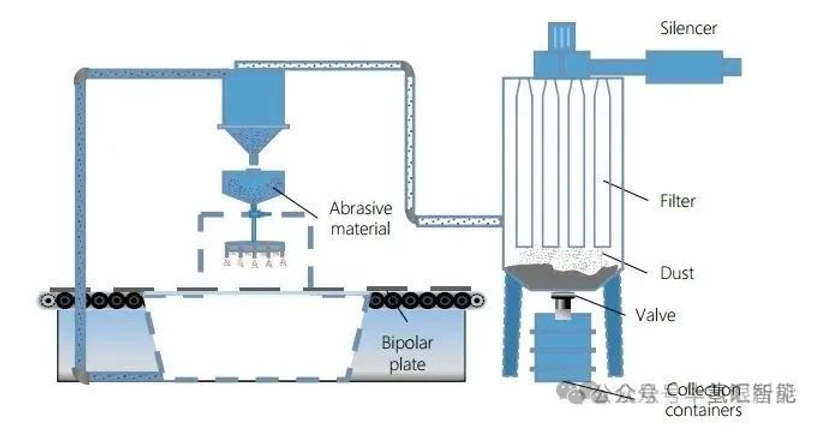
1. Sandblasting (optional)
· Purpose: To increase the surface roughness of bipolar plates and improve the adhesion of subsequent coatings.
· Usually considered a preliminary step.
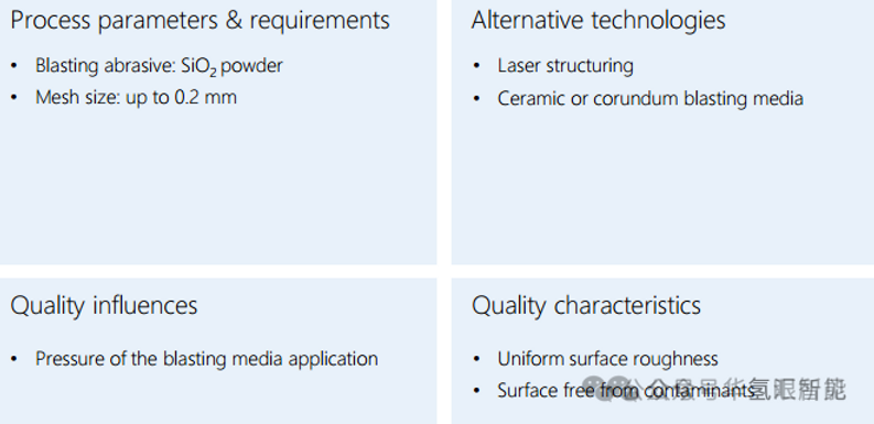
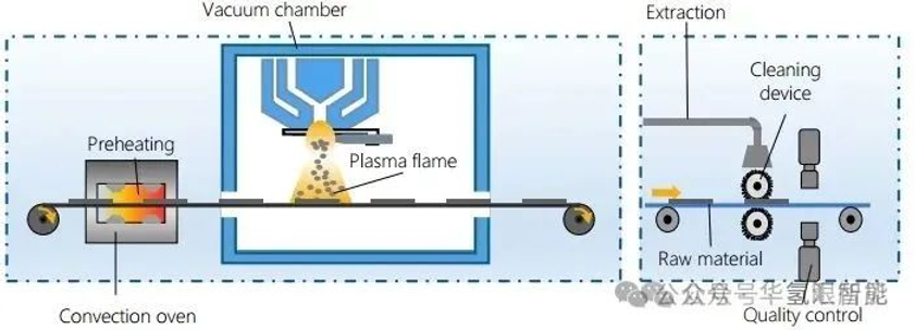
2. Plating
· Purpose: To enhance the corrosion resistance of bipolar plates (high potential environment).
· Method: Vacuum plasma spraying (VPS) is commonly used due to its high degree of automation and low cost.
· process:
1. Preheat the substrate to improve adhesion.
2. In a vacuum chamber (at a low pressure of approximately 50 mbar), an argon/nitrogen/hydrogen plasma is used to deposit a coating metal (such as niobium Nb) onto the surface of the bipolar plate. The vacuum environment prevents oxidation of the coating metal.
3. Coating is usually followed by polishing.
8. Stacking production and pre-assembly
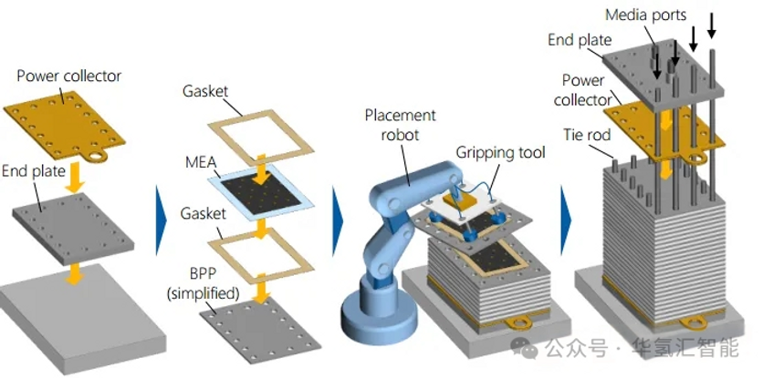
Electrolyzer stack assembly process:
1. Pre-install the lower end plate and lower header.
2. The membrane electrode assembly (MEA), bipolar plate (BPP) and gasket are stacked in sequence to form an independent functional unit surrounded by the bipolar plates.
3. Add the upper manifold and upper end plate, and install the media connection ports.
4. External and internal guide elements ensure the precise alignment of all components.
10. System Production: BOP Integration
· Core: The process involves integrating the fully assembled electrolyser stack into the overall system.
· Space: Large systems are typically assembled within 40-foot (approximately 12-meter) containers.
· Process:
1. - Utilize cranes and other equipment to position large components, (such as stacks, separators, compression pumps, heat exchangers, and tanks, at the installation site.
2. - Connect all fluid circuits (water, hydrogen, oxygen, cooling water) using pipes.
3. - Integrate electrical systems, including power electronics and controls.
4. - Conduct final commissioning and testing.